Friday, 29 September 2017

WONDERFUL DURGA POOJA AT NFCL -DIFFERENT PLACES IN THAT VERY GRAND AT WORKSHOP AROUND 300 ASSOCIATES PERFORMED POOJA BY CORDIAL SUPPORT OF SITE IN-CHARGE SHRI GVS ANAND SIR

IT IS VERY IMPRESSIVE POOJA TO BOOST THE TEAM WORK IN PRESENCE OF SITE IN-CHARGE SIR ,ALL HODs,SHs and ASSOCIATES, USED TO GET INNOVATION WITH NEW ENERGY TO MONITOR THE PLANT OPERATION AND SUSTAIN THE PRODUCTION.ALMOST ALL SECTION DURGA POOJA USED TO BE PERFORMED.
Goddess of War
Victory of Good over Evil
The Invincible One
Fierce form of Mother Goddess


Navdurga, are the nine forms of Durga collectively worshipped by Shakti devotees. Scriptures differ in naming the nine incarnations. Pictures and paintings of the Nava-Durga also varies from region to region. The most widely accepted account of the nine forms of Durga is the one found in the Devi Mahatmya – Sailaputri, Brahmacharini, Chandraghanta, Kushmanda, Skanda Mata, Katyayani, Kalaratri, Maha Gowri and Siddhidayini.
The nine forms of Durga are worshipped during the nine days of Navratri.


Durga, also identified as Adi Parashakti, Devi, Shakti, Bhavani and by numerous other names, is a principal and popular form of Hindu goddess.[6][7][8] She is the warrior goddess, whose mythology centers around combating evils and demonic forces that threaten peace, prosperity and dharma of the good.[7][9] She is the fierce form of the protective mother goddess, willing to unleash her anger against wrong, violence for liberation and destruction to empower creation.[10]

Durga is depicted in the Hindu pantheon as a fearless woman riding a lion or tiger, with many arms each carrying a weapon,[1] often defeating the mythical buffalo demon.[11][12] She appears in Indian texts as the wife of god Shiva, as another form of Parvati or mother goddess.[11][13]

She is a central deity in Shaktism tradition of Hinduism, where she is equated with the concept of ultimate reality called Brahman.[14][9] One of the most important texts of Shaktism is Devi Mahatmya, also called as Durgā Saptashatī, which celebrates Durga as the Goddess, declaring her as the Supreme Being and the creator of the universe.[15][16][17] Estimated to have been composed between 400-600 CE,[18][19][20] this text is considered by Shakta Hindus to be as important scripture as the Bhagavad Gita.[21][22] She has a significant following all over India ,Bangladesh and in Nepal, particularly in its eastern states such as West Bengal, Odisha, Jharkhand, Assam and Bihar. Durga is revered after spring and autumn harvests, specially during the festival of Navratri.


Durga Mahisasuramardini.JPG

The word Durga (दुर्गा) literally means "impassable",[23] "inaccessible",[6] "invincible, unassailable".[25] It is related to the word Durg (दुर्ग) which means "fortress, something difficult to access, attain or pass". According to Monier Monier-Williams, Durga is derived from the roots dur (difficult) and gam (pass, go through).[26] According to Alain Daniélou, Durga means "beyond reach".[27]

The word Durga, and related terms appear in the Vedic literature, such as in the Rigveda hymns 4.28, 5.34, 8.27, 8.47, 8.93 and 10.127, and in sections 10.1 and 12.4 of the Atharvaveda.[26][28][note 1] A deity named Durgi appears in section 10.1.7 of the Taittiriya Aranyaka.[26] While the Vedic literature uses the word Durga, the description therein lacks the legendary details about her that is found in later Hindu literature.[30]

The word is also found in ancient post-Vedic Sanskrit texts such as in section 2.451 of the Mahabharata and section 4.27.16 of the Ramayana.[26] These usages are in different contexts. For example, Durg is the name of an Asura who had become invincible to gods, and Durga is the goddess who intervenes and slays him. Durga and its derivatives are found in sections 4.1.99 and 6.3.63 of the Ashtadhyayi by Pāṇini, the ancient Sanskrit grammarian, and in the commentary of Nirukta by Yaska.[26] Durga as a demon-slaying goddess was likely well established by the time the classic Hindu text called Devi Mahatmya was composed, which scholars variously estimate to between 400 to 600 CE.[18][19][31] The Devi Mahatmya and other mythologies describe the nature of demonic forces symbolised by Mahishasura as shape-shifting and adapting in nature, form and strategy to create difficulties and achieve their evil ends, while Durga calmly understands and counters the evil in order to achieve her solemn goals.[32][33][note 2]

There are many epithets for Durga in Shaktism and nine appellations: Skandamata, Kushmanda, Shailaputri, Kaalratri, Brahmacharini, Chandraghanta and Siddhidatri. A list of 108 names that are used to describe her is very popularly in use by eastern Hindus and is called "Ashtottara Shatanamavali of Goddess Durga"


Thursday, 28 September 2017

Local Weather Report and Forecast For: Kakinada Dated :Sep 28, 2017


Local Weather Report and Forecast For: Kakinada    Dated :Sep 28, 2017
Kakinada
Past 24 Hours Weather Data
Maximum Temp(oC) (Recorded. on 28/09/17)32.0
Departure from Normal(oC)0
Minimum Temp (oC) (Recorded. on 28/09/17)25.0
Departure from Normal(oC)-1
24 Hours Rainfall (mm) (Recorded from 0830 hrs IST
of yesterday to 0830 hrs IST of today)
13.6
Relative Humidity at 0830 hrs (%)86
Relative Humidity at 1730 hrs (%) (Recorded. on 28/09/17)80
Todays Sunset (IST)17:52
Tommorows Sunrise (IST)05:51
Moonset (IST)---
Moonrise (IST)12:28
7 Day's Forecast
DateMin TempMax TempWeather
28-Sep25.033.0Generally cloudy sky with one or two spells of rain or thundershowers
29-Sep25.034.0Generally cloudy sky with one or two spells of rain or thundershowers
30-Sep25.034.0Generally cloudy sky with one or two spells of rain or thundershowers
01-Oct25.033.0Generally cloudy sky with one or two spells of rain or thundershowers
02-Oct25.033.0Generally cloudy sky with one or two spells of rain or thundershowers
03-Oct25.033.0Generally cloudy sky with possibility of rain or Thunderstorm
04-Oct25.033.0Generally cloudy sky with possibility of rain or Thunderstorm


VISCOSITY

THANKS TO SHRI JKP SIR QUALITY CONTROL UNDER KSS DISCUSSION

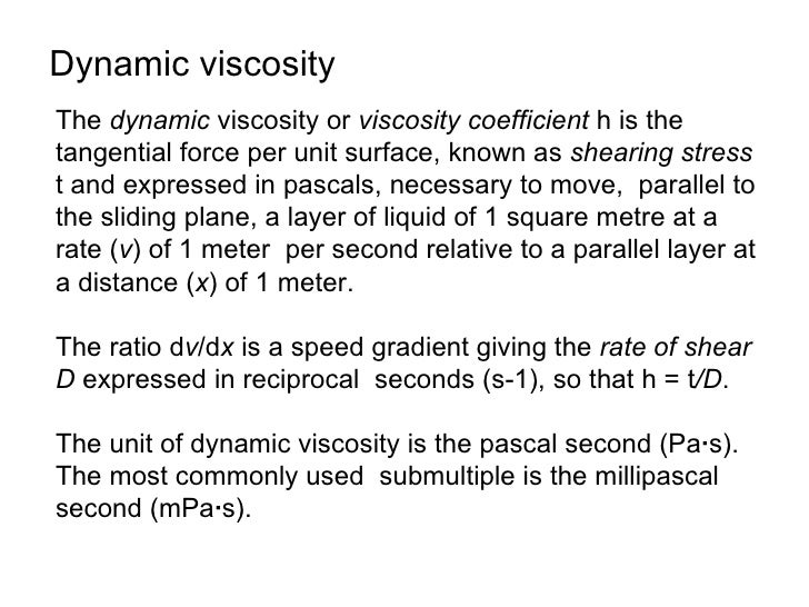
Dynamic viscosityThe dynamic viscosity or viscosity coefficient h is thetangential force per unit surface, known as sheari...
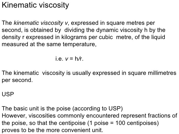
Kinematic viscosityThe kinematic viscosity v, expressed in square metres persecond, is obtained by dividing the dynamic vi...
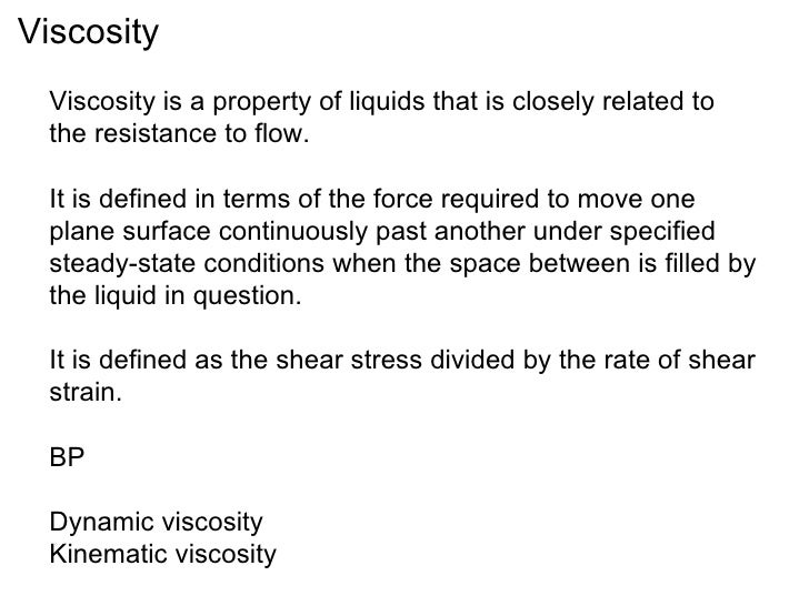
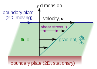
Viscosity  Viscosity is a property of liquids that is closely related to  the resistance to flow.  It is defined in terms ...Image result for viscosityImage result for viscosityImage result for viscosityImage result for viscosityImage result for viscosity


Wednesday, 27 September 2017

Dr. Harshvardhan Inaugurates Exhibition On Swachhata Hi Seva

Dr. Harshvardhan Inaugurates Exhibition On Swachhata Hi Seva
Minister for Science & Technology and Earth Sciences and Environment, Forest and Climate change, Dr. Harshvardhan inaugurated an exhibition on Swachhata Hi Seva, organized by Ministry of Science & Technology and Ministry of Earth Sciences and coordinated by Council of Scientific and Industrial Research (CSIR).

The exhibition highlighted the technologies and products developed by these science ministries which are being used for Swachhata Abhiyan of Government of India. The exhibition comprised of demonstration of models, and technologies explaining scientific and technological intervention brought in by these ministries.

CSIR showcased the technology of Terafil and tiles made from plastic waste. Terafil is a low cost burnt red clay porous media (disc/candle), used for filtration & treatment of turbid raw water into clean drinking water for domestic/ community applications.   It can be fixed with any container for purification of water.    It operates without electricity, spent water and sludge management.  

Tiles made from waste plastics were demonstrated. Novel features of these tiles include its high mechanical strength, flame retardency, UV protection and anti-static response. These tiles can be used in designing of structure like Smart Toilets that will be beneficial for the villages and large section of the society.

Several posters depicting the technological intervention made for Swachh Bharat were also displayed.  CSIR undertook the study of special properties of Ganga water which include medicinal and anti-bacterial properties. Rich and diverse population of bacteriophages against various type of bacteria were observed in Ganga water. CSIR monitored sediment and water quality of river Ganga from Gomukh to Gangasagar at 70 locations and also 35 locations along river Narmada and river Yamuna for comparative study.

CSIR demonstrated, how mobile van developed by its Laboratory monitors air quality and provide instantaneous data relating to vehicular emissions. Data helps to identify the areas with high level of air pollution and suggest remedial measures to contain air pollution. CSIR also displayed technology for eco-restoration of mine through use of biotechnology.

CSIR has developed Phytorid Waste Water Treatment technology. The technology involves a constructed wetland exclusively designed for the treatment of municipal, urban, agricultural and industrial wastewater.     The phytorid technology can be constructed in series and parallel modules / cells depending on the land availability and quantity of wastewater to be treated.  

 Multi-sector application of climate and weather informatics which is helpful for society and industries was also displayed.

CSIR-CLRI has developed and deployed the technologies for end-of-pipe treatment for the waste generated in leather processing and increasing the efficiency of the common effluent treatment plants.  

 The autonomous institutes of Department of Science & Technology(DST) exhibited the technologies they developed that are relevant to Swachhata Mission as part of ‘Swachhta Hi Seva’.
The Institute of Nanoscience & Technology, Mohali has developed a technology for low cost water purification system for domestic and industrial waste water treatment.  It uses nano absorbents to treat water from toxic wastes.
The other technology is for recovering Nanostructured materials from the used batteries waste and industrial waste using environment friendly approach. The materials recovered include metal oxide, silica, sodium nitrate and sodium carbonate which can be used for treatments of organic pollutants in water.
National Innovation Foundation showcased ideal technologies developed by innovators for waste collection to fulfill the objective of “Swachh Bharat Abhiyan”.  It can be boon for sanitation workers as it reduces effort and time but increases coverage and frequency of area being cleaned. The first one is Wrapper Picker, designed to collect light weight garbage except fine dust. It is battery operated device with an in-built provision to indicate the status of charge in battery. The other one is INSPIRE awarded innovation called Manual Waste Lifting and Dumping Device. It is helpful in providing manual and mobile waste tool with picking and dumping facility to make it more effective. 
Vigyan Prasar  showcased sanitation and hygienic practices in a very simplified manner  that should be carried out in day to day lives by  different sections of society.
Department of Bio-Technology (DBT)   showcased a range of technologies like clean energy, river cleaning initiatives, technologies to clean up waste water, supporting bio-toilets and a range of other waste management & utilization technologies. 
India’s first home grown technology to convert biomass to ethanol with speed and efficiency was developed by the Institute of Chemical Technology, Mumbai. The rate of conversion of biomass to ethanol in this technology is faster than other technologies currently available in the international market. The technology has been transferred to BPCL and HPCL for building commercial scale biomass to ethanol plants expected by 2018
Photo of the Ethanol producing plant at Kashipur
Novel bio-toilet technologies that promises cleaner India
Innovative bio-toilet ideas generated through Reinvent the Toilet Challenge India was launched by the Grand Challenges India framework. Under this initiative 6 new bio-toilet technologies have been supported. Around 100 toilets have been set up to demonstrate the technology. Several bio-toilets set up in schools of North Eastern States. The technologies focused on redesigning the toilet seat, making it more eco-friendly. Off-grid, self-sustained, modular, electronic toilet have been innovated for slums, with solar energy for Indian weather and integrated with mixed waste processing unit & water, energy/ fertilizer recovery. Septic tanks have been empowered by converting them into decentralized wastewater treatment system.
Bio-toilet technologies
River cleaning technologies
DBT collaborated with the Dutch to help clean Delhi’s Barapullah drain. This initiative would later expand to efforts for cleaning Yamuna River. In the next five years, a wastewater treatment plant to make the filthy water potable is scheduled to be set up. The plant will also remove heavy metals from the water for reuse. Most of the technology choices for cleaning the Barapullah drain would be biological in nature.
Sampling of water at the site/ Laboratory being set up at the site
Green remediation technology for wastewater
DBT’s support helped develop green remediation process for textile dyes in wastewaters. The technology was developed by Shivaji University, Kolhapur. Aquatic plants were identified that can effectively clean up textile dyes & used for effluent treatment. By-products after treatment showed reduced toxicity.

The green remediation technology & the cleaned up waste water
Waste treatment technologies galore
These technologies for waste management and treatment include one for removing organic waste from municipal waste water at 95 percent efficiency called anaerobic membrane bioreactor, one for treatment of wastewater from distillery industry with enhanced bio-gas yield called Vortex Diode based Cavitation Devices,  a novel, robust, versatile, modular, compact and cost effective appliance for decentralized waste processing which can obviate requirements for costly disposal and treatment system for entire cities or regions, a treatment system that can tackle domestic septage, municipal solid waste and landfill leachate—a major challenge for sustainable cities.
*

India Japan Cooperation in Rail Safety

India Japan Cooperation in Rail Safety
Taking the technical cooperation in Rail Safety ahead, a team/ Mission of Safety experts from Japan concluded its second visit early this month. This team comprised of representatives of Japan’s Ministry of Land, Infrastructure, Transport and Tourism (MLIT), JICA (Japan International Cooperation Agency) and railway operators etc. This mission discussed detailed scope of cooperation. This Mission visited Indian Railway’s (IR) coach/wagon/loco maintenance facilities. The Mission also observed rail welding and track maintenance practices followed by IR.

Earlier, in response to the request from Indian Railways, MLIT deputed a team of Japanese Railway experts to India to assess incidents of rail breakage and suggest measures to improve safety in train operations. The first meeting was held on 9.1.2017 with Japanese Experts. Following this first visit, a separate Memorandum of Cooperation (MoC) on Railway safety was signed on 17.2.2017 between Ministry of Railways, Government of India (GoI) and MLIT, Japan to cover the area adequately.

The MoC envisages cooperation in Rail Safety on area such as maintenance of Track (welding, rail inspection, track circuit etc.) and rolling stock maintenance. ‘Capacity Development’ has been taken as a Technical Cooperation project under the MoC to develop Indian Railways’ capacity in respect of the above identified areas. These areas have been incorporated in the Terms of Reference of cooperation.

Japanese Railways is one of the oldest Rail system in the world. Japan is the pioneer in the High Speed Rail ‘Shinkansen’. Japanese Railways has an impeccable record with Safety. Ministry of Railways (GoI) had requested Japan’s Ministry of Land, Infrastructure, Transport and Tourism (MLIT) for technical cooperation in Rail Safety.

The cooperation will facilitate exchange of information and visit of experts from both sides. A workshop is proposed to be organised in the first week of Nov’2017 in association with Japanese experts. 

Tuesday, 26 September 2017

The Fertilizer Association of India (FAI)


The Fertilizer Association of India (FAI)

The Fertiliser Association of India(link is external) (FAI) is a non-profit and non-trading company representing mainly the fertiliser manufacturers, distributors, importers, equipment manufacturers, research institutes and suppliers of inputs. The Association was established in 1955 with the objective of bringing together all parties concerned with the production, marketing and use of fertilisers with a view to:
  • Assist the industry in improving its operative efficiency
  • Find solutions to the problems facing the fertiliser industry and agriculture
  • Promote the balanced and efficient use of fertiliser
  • Encourage the use of more and better plant foods
  • Promote consideration and discussion of all questions that contribute to sound agricultural practices
FAI has access to the information on Indian fertilizer industry covering almost all manufacturers. Information on their profile, performance, capacity utilization, energy consumption, energy conservation measures implemented and their impact, constraints in further implementation of energy saving measures, technology licensors, equipment suppliers are avaiable with the organization, partly as published data and partly  as confidential information.
FAI is engaged in monitoring of performance of fertiliser plants with respect to various operational parameters like energy consumption, water consumption, causes for downtime in plants, loss time accidents and other causes and concentration of pollutants in effluents and emissions. FAI also carries studies related to energy and environment. Status papers are prepared , presented and published. Benchmarking exercises are also carried out periodically.
FAI also provides platform for exchange of information on all aspects related to fertilizer production through a number of Group Discussions, Workshops, Seminars and Symposia. FAI also brings out a monthly publication, “Indian Journal of Fertilisers”, which provides opportunity to exchange experience on various aspects of fertiliser production, distribution and consumption.
FAI is working as the sector expert agency to Bureau of Energy Efficiency (BEE) for implementation of Perform Achieve Transfer Scheme.  Under this scheme, 29 designated consumers (DC’s) have been identified. This covers all the ammonia / urea manufacturing plants. All DC’s have submitted their performance data to FAI / BEE in prescribed Form.  FAI also assisted BEE in arriving at targets for reduction in energy consumption. 
Association of FAI in developing the “ Action to Achieve (A2A) Toolkit 
FAI associated itself with the development of an energy assessment tool kit called as Assessment to Action (A2A), developed by IIP & ICF Marbek. The Toolkit was first developed for  Chinese plants and later modified and fine tuned for Indian fertilizer industry.  
All the improvement measures in the toolkit’s library were reviewed and more feasible options were added. For each of the identified technological options, FAI provided realistic data regarding costs, energy saving, cost benefit analysis etc. The modified Toolkit was further subjected to field testing / validation and its fine tuning was carried out by visiting two plants. 

The Fertilizer Association of India (FAI) Information


The chemical and petrochemical sector is the largest industrial energy consumer. Ammonia production is responsible for about 17% of the energy consumed in this sector. In 2004, the ammonia manufacturing industry consumed 5.6 EJ of fossil fuels, of which 2.7 EJ was for energy and 2.9 EJ for feedstock use.1 Although the energy use per tonne of ammonia has decreased by 30% over the last thirty years, adopting best available technologies (BAT) worldwide can further reduce energy use by 20-25%1, 2 and decrease greenhouse gas emissions by 30%.2

Technology or MeasureEnergy Savings PotentialCO2 Emission Reduction Potential Based on LiteratureCostsDevelopment Status
Using Improved Materials for Reformer Tubes
Replacement of the reformer tubes in the Indian plant required an investment of Rs. 50 million. The payback time was 40 months (PCRA(link is external),, 2009 p.335).
Indian Flag  Investments for a 1 300 tpd plant are around US $ 2 million [2011 values] (FAI, 2013).
Commercial
Heat Recovery from Reformer Flue Gas
Reducing the stack temperature by 100˚C will result in energy savings of approximately 0.4 GJ/ t NH3 (Christensen, 2001).
Indian Flag By installing a feed pre-heat coil in the low temperature convection section of the reformer flue gas duct, a plant in India was able to reduce flue gas temperature of the reformer from 170˚C to 148˚C and eliminated the need for a fired heater, resulting in energy savings of 0.17 GJ/t NH3 (Nand and Goswami, 2009(link is external)). 
Indian Flag Another Indian installed a natural gas heating coil to recover the heat from the reformer flue gas. The reformer flue gas temperature was reduced from 190˚C to 160˚C, saving 0.18 GJ/t NH(Nand and Goswami, 2009(link is external)). 
At an ammonia plant in Pakistan, a demineralized water preheating coil was installed to recover heat from the flue gas (240˚C). The temperature of the flue gas was lowered to 137˚C, recovering approximately 44 GJ/hour of waste heat from the flue gases (Yousaf, 2011)
Heat recovery in the Pakistani plant saved $ 2 Million/year (Yousaf, 2011)
Indian Flag For a 1 300 tpd plant, the required investments are estimated to be around US $ 700 000 [2008 values] (FAI, 2013).
Commercial
Using Improved Catalyst Designs for Primary ReformingCommercial
Improving the Design for Induced Draft Fan Ducts
Indian Flag For a 1 500 tpd plant, investments are estimated at around US $ 200 000 (FAI, 2013).
Commercial
Heat Exchange Autothermal Reforming
The investment cost are stated to be 303 Yen/tonne ammonia, resulting in a payback time of one year (1999 figures) (ECCJ, 1999, 148).
Commercial
Increasing Reformer Operating PressureCommercial
Modification of Burners in Primary Reforming
Indian Flag  Replacement of burner nozzles for a 1 500 tpd plant is estimated to cost around US $ 0.4 million [2012 values] (FAI, 2013)
Commercial
Using an Adiabatic Pre-reformer
Energy consumption can be reduced by 4-10% (IPTS/EC, 2007; Nieuwlaar, 2001; Patel et al., unknown date)
Dutch flag In Netherlands, a plant in Rozenburg, energy savings of about 4% were realized with the installation of an adiabatic pre-reformer. (Worrell and Blok, 1994). 
For a 2 000 t/day plant, the investment cost associated with the installation of a pre-reformer is reported to ¥280 million, resulting in a payback time of 1.7 years (ECCJ, 1999 p. 156). 
According to Nieuwlaar (2001) the investment cost is estimated at €7.5/GJ. 
Dutch flag For the plant in Netherlands, the installation costs for the adiabatic pre-reformer was estimated as $6/tonne ammonia, and the payback time was estimated to be  one to three years (in 1990 dollars) (Worrell and Blok, 1994).
Indian Flag For a 1500 tpd plant, the investments are in the range of US $ 10 million (2000 values) (FAI, 2013).
Commercial
Insulation of Reformer Furnace
An assessment for an Australian ammonia plant estimated that the payback time for improving insulation on reformer furnace will have a payback time of less than one year (Australian Government, 2009). 
Commercial
Improved Design of Secondary Reformer Burner
Indian Flag The cost of replacing burner nozzles in a 1 500 tpd plant is reported to be around US $500 000(FAI, 2013).
Commercial
Using Improved Catalyst Designs for Secondary ReformingCommercial
Shifting Reformer Duty
This measure increases the capital costs (FAI, 2013). 
Commercial
High Emissivity Coating of Radiant Section Refractory
Indian Flag For a 1 500 tpd plant, the implementation costs are estimated to be around US $ 25 000 FAI, 2013). 
Commercial
Heat Exchanger Reformer
Lower Steam to Carbon Ratio on ReformerCommercial
Installing a Feed Gas SaturatorCommercial
Increasing Mixed Feed Preheat Temperature
Indian Flag For a 1 500 tpd plant, an investment in the range of US $ 500 000 is required to preheat fuel gas using low grade recovered heat (FAI, 2013)..
Commercial

Steam Reforming


Steam Reforming

In steam reforming, hydrogen is produced by reforming the hydrocarbon feedstock, producing synthesis gas containing a mixture of carbon monoxide and hydrogen. The carbon monoxide is then reacted with steam in the water-gas-shift reaction to produce carbon dioxide and hydrogen. The carbon dioxide is recovered for urea production, exported as co-product, or vented to the atmosphere. In the final synthesis loop, the hydrogen reacts with nitrogen to form ammonia. 
In steam reforming ammonia plants there is a surplus of high-level heat that is produced in primary reforming, secondary reforming, shift conversion and ammonia synthesis. Most of the waste heat is recovered for producing high pressure steam that is used in turbines for driving compressors, pumps and fans. In general, all the high pressure steam will be used in steam turbines for driving the synthesis gas compressor. Modern steam reforming ammonia plants do not import energy for driving the mechanical equipment. Energy is in many cases exported in the form of steam or electricity to other consumers (IPTS/EC, 2007).  
The natural gas use in a an ammonia plant using the steam reforming process ranges between 28 and 35.5 GJ/tonne, of which about 20-22 GJ/tonne of ammonia is used as feedstock, 7.2-9.0 GJ/tonne is fuel consumed in the primary reformer, and the remaining 0.5-4.2 GJ/tonne is used in auxiliary boilers and others. Table below shows the typical breakdown of energy use in steam reforming ammonia plants. 
Estimated energy use breakdown for a typical ammonia plant using natural gas as a feedstock (Appl, 1998; EFMA 2000; Worrell et al. 2000; IPTS/EC 2007; Saygin, 2013)
Natura Gas
(GJ/t NH3
Heat Input/Output
(GJ/t NH3)
Primary reformer feed20.4 - 22.3
Primary reformer7.2 - 9.03.0 - 4.5
Secondary reformer0.0
Waste heat boiler-5.0 - -6.0
Shift and CO2 removal0.8 - 1.2
Methanator
Synthesis loop-2.5 - -3.0
Auxiliary boiler0.3 - 3.5-0.2 - 3.0
Turbines/compressors3.9 - 6.3
Other (e.g. flare0.2 - 0.7
Total28.1 - 35.50.0

There are also a number of steam reforming configurations offered by different technology providers, and currently considered as best available technologies. These include the following:
  • Advanced conventional primary reforming with high duty primary reforming and stoichiometric process air in the secondary reformer. Processes with this configuration are the Kellogg Low-Energy Ammonia Process, the Haldor Topsoe process, the Uhde process, the LEAD process, the Exxon Chemical Process, the Fluor process and the Lumus process (Ullmann’s, 2011).
  • Steam reforming with mild condition in the primary reformer and use of excess air in the secondary reformer. Processes with this configuration are the Braun Purifier process, the ICI AMV process, the Foster Wheeler AM2 process, the Humphreys & Glascow BYAS process, the Jacob Plus Ammonia Technology the Montedison Low-pressure process and the Kellogg’s LEAP process (Ullmann’s, 2011).
  • Heat exchange autothermal reforming with a process gas heat exchange reformer and a separate secondary reformer, or in combination with an autothermal reformer that uses excess or enriched air. Processes with this configuration are the ICI LCA process and the Chiyoda process (Ullmann’s, 2011).
There are also a number of processes in which there is no use of a secondary reformer in which the nitrogen is supplied by an air separation unit. Some examples are the Linde LAC process and the Humphreys & Glasgow MDF process. Claimed energy use values of the different processes are provided in Table below. 
Energy Use in Advanced Steam Reforming Configurations (Ullmann’s, 2011)
Process NameEnergy Use
(GJ/t NH3)
Advanced conventional primary reforming
Kellogg Low-Energy Ammonia Process27.9 (27.01)
Haldor Topsoe Process27.9
Uhde Process28.0  (27.0)
LEAD Process29.3
Exxon Chemical Process29.0
Fluor Process32.0
Lummus Process29.6-33.5
Processes with reduced primary refiner firing
Braun Purifier Process28.0 (27.01)
ICI AMV Process28.5
Foster Wheeler AM2 Process29.3
Humphreys & Glasgow BYAS Process28.7
Jacobs Plus Ammonia Technology28.8 (26.81)
Montedison Low-Pressure Process28.1
Kellogg’s LEAP Process<28.0
Processes without a primary reformer
ICI LCA Process29.3
Kellogg Brown and Root (KBR) KAAPplus Process27.2
Chiyoda ProcessN/A
Processes without a secondary reformer
KTI PARC Process29.3-31.8
Linde LAC Process28.5 (29.32)
Humphreys & Glasgow MDF Process32.82
1: Energy use when steam is exported
2: Energy use when CO2 is recovered. 
Conventional steam reforming of natural gas includes desulphurization, primary reforming and secondary reforming processes. 
Desulphurization: 
The feedstock used for the production of ammonia may contain sulphur and sulphur compounds which are harmful for the catalyst used in subsequent process steps and therefore need to be removed. Typically, feedstocks may contain up to 5 mg S/Nm3 of sulphur compounds. In desulphurization, the pre-heated (350-400oC) and untreated feed-gas enters a vessel that usually contains a cobalt molybdenum catalyst where the sulphur compounds are hydrogenated to H2S. The hydrogen needed for the reaction is usually recycled from the synthesis section. The hydrogenated sulphur compounds are then adsorbed on pelletized zinc oxide. After desulphurization, the feed-gas sulphur concentration drops to less than 0.1 ppm. 
Primary Reforming:
The feed-gas, after being treated in a desulphurization vessel, is mixed with process steam. The preheated mixture enters the primary reformer at a temperature of 400-600oC. In certain new and revamped ammonia plants the preheated steam/gas mixture is passed through an adiabatic pre-reformer before entering the primary reformer, where it is then reheated in the convection section (EFMA, 2000). 
Primary reformers consist of a large number of high-nickel chromium alloy tubes which are filled with a nickel-containing reforming catalyst (see Figure 3). In conventional steam reforming, the hydrocarbon conversion rate in the primary reformer is about 60%. The reaction is highly endothermic: 
Natural gas or other types of burners provide heat to the process. About half of the heat supplied to the primary reformer is consumed in the reaction. The remaining half is contained in the flue gases and used in the convection section of the reformers for the preheating of process streams. The flue gases leaving the primary reformer convection section compose the most significant source of the plant’s emissions. These emissions mainly consist of CO2, NOx, and small amounts of SO2 and CO (EFMA, 2000).
The typical fuel use in the primary reformer (including steam generation) ranges between 7.2 and 9.0 GJ/tonne of ammonia (IPTS/EC, 2007). Natural gas consumption in energy efficient ammonia plants is about 6.8 GJ/tonne of ammonia (Ullmann’s, 2011).
Secondary Reforming: 
In secondary reforming the nitrogen needed for the production of ammonia is added and the reforming of the hydrocarbon feed is completed (only about 60% of the feed-gas was reformed in the primary reformer). In order to increase the conversion rate, high temperatures are required. This is achieved with the internal combustion of part of the reaction gas and the process air, which is also the source of nitrogen, before it passes over to the nickel containing catalysts. The supplied air is compressed and heated at the convection section of the primary reformer at a temperature of 500-600oC. The gas outlet temperature is about 1000oC and about 99% of the primary reformer hydrocarbon feed is converted. The residual methane content is about 0.2-0.3% (dry gas base). Heat is removed with the use of a waste heat boiler and the gas is cooled down to approximately 330-380oC (IPTS/EC, 2007). 

Steam ReformingSchematic