Oil Viscosity - How It's Measured and Reported
According to the
Society of Tribologists and Lubrication Engineers (STLE), viscosity is
one of an oil’s most important physical properties. It is often one of
the first parameters measured by most oil analysis labs because of its
importance to oil condition and lubrication. But what do we really mean
when we talk about an oil’s viscosity?
A lubricating oil’s viscosity is typically measured and defined in two ways, either based on its kinematic viscosity or its absolute (dynamic) viscosity. While the descriptions may seem similar, there are important distinctions between the two.
An oil’s kinematic viscosity is defined as its resistance to flow and shear due to gravity. Imagine filling a beaker with turbine oil and another with a thick gear oil. Which one will flow faster from the beaker if it is tipped on its side? The turbine oil will flow faster because the relative flow rates are governed by the oil’s kinematic viscosity.
Now let’s consider absolute viscosity. To measure absolute viscosity, insert a metal rod into the same two beakers. Use the rod to stir the oil, and then measure the force required to stir each oil at the same rate. The force required to stir the gear oil will be greater than the force required to stir the turbine oil. Based on this observation, it might be tempting to say that the gear oil requires more force to stir because it has a higher viscosity than the turbine oil. However, it is the oil’s resistance to flow and shear due to internal friction that is being measured in this example, so it is more correct to say that the gear oil has a higher absolute viscosity than the turbine oil because more force is required to stir the gear oil.
For Newtonian fluids, absolute and kinematic viscosity are related by the oil’s specific gravity. However, for other oils, such as those containing polymeric viscosity index (VI) improvers, or heavily contaminated or degraded fluids, this relationship does not hold true, and can lead to errors if we are not aware of the differences between absolute and kinematic viscosity. For a more detailed discussion on absolute versus kinematic viscosity, refer to the article “Understanding Absolute and Kinematic Viscosity” by Drew Troyer.
Capillary Tube Viscometer Test Method
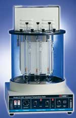
The most common method of determining kinematic viscosity in the lab utilizes the capillary tube viscometer (Figure 1). In this method, the oil sample is placed into a glass capillary U-tube and the sample is drawn through the tube using suction until it reaches the start position indicated on the tube’s side. The suction is then released, allowing the sample to flow back through the tube under gravity. The narrow capillary section of the tube controls the oil’s flow rate; more viscous grades of oil take longer to flow than thinner grades of oil. This procedure is described in ASTM D445 and ISO 3104.
Because the flow-rate is governed by resistance of the oil flowing under gravity through the capillary tube, this test actually measures an oil’s kinematic viscosity. The viscosity is typically reported in centistokes (cSt), equivalent to mm2/s in SI units, and is calculated from the time it takes oil to flow from the starting point to the stopping point using a calibration constant supplied for each tube.
In most commercial oil analysis labs, the capillary tube viscometer method described in ASTM D445 (ISO 3104) is modified and automated using a number of commercially available automatic viscometers. When used correctly, these viscometers are capable of reproducing a similar level of accuracy produced by the capillary tube manual viscometer method.
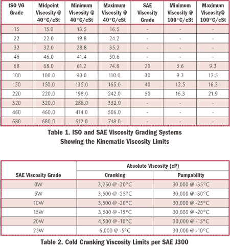
Stating an oil’s viscosity is meaningless unless the temperature at which the viscosity was measured is defined. Typically, the viscosity is reported at one of two temperatures, either 40°C (100°F) or 100°C (212°F). For most industrial oils, it is common to measure kinematic viscosity at 40°C because this is the basis for the ISO viscosity grading system (ISO 3448). Likewise, most engine oils are typically measured at 100°C because the SAE engine oil classification system (SAE J300) is referenced to the kinematic viscosity at 100°C (Table 1). Additionally, 100°C reduces the rise of measurement interference for engine oil soot contamination.
Rotary Viscometer Test Method
A less common method of determining an oil’s viscosity utilizes a rotary viscometer. In this test method, the oil is placed in a glass tube, housed in an insulated block at a fixed temperature (Figure 2). A metal spindle is then rotated in the oil at a fixed rpm, and the torque required to rotate the spindle is measured. Based on the internal resistance to rotation provided by the shear stress of the oil, the oil’s absolute viscosity can be determined. Absolute viscosity is reported in centipoise (cP), equivalent to mPa·s in SI units. This method is commonly referred to as the Brookfield method and is described in ASTM D2983.
While less common than kinematic viscosity, absolute viscosity and the Brookfield viscometer are used in formulating engine oils. For example, the “W” designation, which is used to denote oils that are suitable for use at colder temperatures, is based in part on the Brookfield viscosity at various temperatures (Table 2).
Based on SAE J300, a multigrade engine oil that is designated as SAE 15W-40 must therefore conform to the kinematic viscosity limits at elevated temperatures according to Table 1 and the minimum requirements for cold cranking as shown in Table 2.
Viscosity Index
One other important property of an oil is viscosity index (VI). The viscosity index is a unitless number, used to indicate the temperature dependence of an oil’s kinematic viscosity. It is based on comparing the kinematic viscosity of the test oil at 40°C, with the kinematic viscosity of two reference oils - one of which has a VI of 0, the other with a VI of 100 (Figure 3) - each having the same viscosity at 100ºC as the test oil. Tables for calculating VI from the measured kinematic viscosity of an oil at 40°C and 100°C are referenced in ASTM D2270.
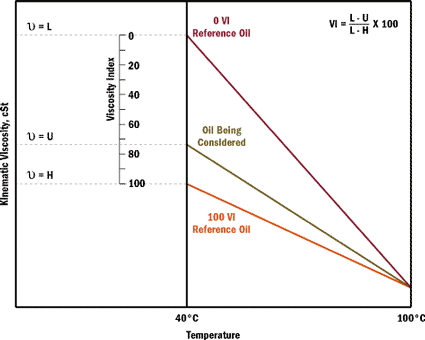
Figure 3. Determination of Viscosity Index (VI)
Figure 3 shows that
an oil that has a smaller change in kinematic viscosity with temperature
will have a higher VI than an oil with a greater viscosity change
across the same temperature range.
For most paraffinic, solvent-refined mineral-based industrial oils, typical VIs fall in the range of 90 to 105. However, many highly refined mineral oils, synthetics and VI improved oils have VIs that will exceed 100. In fact, PAO-type synthetic oils typically have VIs in the range 130 to 150.
Viscosity Monitoring and Trending
Monitoring and trending viscosity is perhaps one of the most important components of any oil analysis program. Even small changes in viscosity can be magnified at operating temperatures to the extent that an oil is no longer able to provide adequate lubrication. Typical industrial oil limits are set at ±5 percent for caution, and ±10 percent for critical, although severe- duty applications and extremely critical systems should have even tighter targets.
A significant reduction in viscosity can result in:
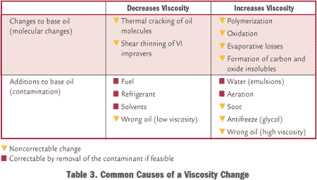 Viscosity changes
may require additional tests, such as: acid number (AN) or Fourier
transform infrared spectroscopy (FTIR), to confirm incipient oxidation;
contaminant testing to identify signs of water, soot or glycol ingress;
or other less commonly used tests, such as the ultracentrifuge test or
gas chromatography (GC), to identify a change in the base oil chemistry.
Viscosity is an important physical property that must be monitored and controlled carefully because of its impact on the oil and the oil’s impact on equipment life. Whether measuring viscosity onsite using one of many onsite oil analysis instruments capable of determining viscosity changes accurately, or whether sending samples routinely to an outside lab, it is important to learn how viscosity is determined, and how changes can impact equipment reliability. A proactive approach must be taken to determine the condition of the equipment’s lifeblood - the oil!
A lubricating oil’s viscosity is typically measured and defined in two ways, either based on its kinematic viscosity or its absolute (dynamic) viscosity. While the descriptions may seem similar, there are important distinctions between the two.
An oil’s kinematic viscosity is defined as its resistance to flow and shear due to gravity. Imagine filling a beaker with turbine oil and another with a thick gear oil. Which one will flow faster from the beaker if it is tipped on its side? The turbine oil will flow faster because the relative flow rates are governed by the oil’s kinematic viscosity.
Now let’s consider absolute viscosity. To measure absolute viscosity, insert a metal rod into the same two beakers. Use the rod to stir the oil, and then measure the force required to stir each oil at the same rate. The force required to stir the gear oil will be greater than the force required to stir the turbine oil. Based on this observation, it might be tempting to say that the gear oil requires more force to stir because it has a higher viscosity than the turbine oil. However, it is the oil’s resistance to flow and shear due to internal friction that is being measured in this example, so it is more correct to say that the gear oil has a higher absolute viscosity than the turbine oil because more force is required to stir the gear oil.
For Newtonian fluids, absolute and kinematic viscosity are related by the oil’s specific gravity. However, for other oils, such as those containing polymeric viscosity index (VI) improvers, or heavily contaminated or degraded fluids, this relationship does not hold true, and can lead to errors if we are not aware of the differences between absolute and kinematic viscosity. For a more detailed discussion on absolute versus kinematic viscosity, refer to the article “Understanding Absolute and Kinematic Viscosity” by Drew Troyer.
 |
|
Figure 1. Capillary Tube Viscometer
|
The most common method of determining kinematic viscosity in the lab utilizes the capillary tube viscometer (Figure 1). In this method, the oil sample is placed into a glass capillary U-tube and the sample is drawn through the tube using suction until it reaches the start position indicated on the tube’s side. The suction is then released, allowing the sample to flow back through the tube under gravity. The narrow capillary section of the tube controls the oil’s flow rate; more viscous grades of oil take longer to flow than thinner grades of oil. This procedure is described in ASTM D445 and ISO 3104.
Because the flow-rate is governed by resistance of the oil flowing under gravity through the capillary tube, this test actually measures an oil’s kinematic viscosity. The viscosity is typically reported in centistokes (cSt), equivalent to mm2/s in SI units, and is calculated from the time it takes oil to flow from the starting point to the stopping point using a calibration constant supplied for each tube.
In most commercial oil analysis labs, the capillary tube viscometer method described in ASTM D445 (ISO 3104) is modified and automated using a number of commercially available automatic viscometers. When used correctly, these viscometers are capable of reproducing a similar level of accuracy produced by the capillary tube manual viscometer method.
Stating an oil’s viscosity is meaningless unless the temperature at which the viscosity was measured is defined. Typically, the viscosity is reported at one of two temperatures, either 40°C (100°F) or 100°C (212°F). For most industrial oils, it is common to measure kinematic viscosity at 40°C because this is the basis for the ISO viscosity grading system (ISO 3448). Likewise, most engine oils are typically measured at 100°C because the SAE engine oil classification system (SAE J300) is referenced to the kinematic viscosity at 100°C (Table 1). Additionally, 100°C reduces the rise of measurement interference for engine oil soot contamination.

 |
|
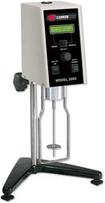
Figure 2. Rotary Viscometer
|
A less common method of determining an oil’s viscosity utilizes a rotary viscometer. In this test method, the oil is placed in a glass tube, housed in an insulated block at a fixed temperature (Figure 2). A metal spindle is then rotated in the oil at a fixed rpm, and the torque required to rotate the spindle is measured. Based on the internal resistance to rotation provided by the shear stress of the oil, the oil’s absolute viscosity can be determined. Absolute viscosity is reported in centipoise (cP), equivalent to mPa·s in SI units. This method is commonly referred to as the Brookfield method and is described in ASTM D2983.
While less common than kinematic viscosity, absolute viscosity and the Brookfield viscometer are used in formulating engine oils. For example, the “W” designation, which is used to denote oils that are suitable for use at colder temperatures, is based in part on the Brookfield viscosity at various temperatures (Table 2).
Based on SAE J300, a multigrade engine oil that is designated as SAE 15W-40 must therefore conform to the kinematic viscosity limits at elevated temperatures according to Table 1 and the minimum requirements for cold cranking as shown in Table 2.
Viscosity Index
One other important property of an oil is viscosity index (VI). The viscosity index is a unitless number, used to indicate the temperature dependence of an oil’s kinematic viscosity. It is based on comparing the kinematic viscosity of the test oil at 40°C, with the kinematic viscosity of two reference oils - one of which has a VI of 0, the other with a VI of 100 (Figure 3) - each having the same viscosity at 100ºC as the test oil. Tables for calculating VI from the measured kinematic viscosity of an oil at 40°C and 100°C are referenced in ASTM D2270.

Figure 3. Determination of Viscosity Index (VI)
For most paraffinic, solvent-refined mineral-based industrial oils, typical VIs fall in the range of 90 to 105. However, many highly refined mineral oils, synthetics and VI improved oils have VIs that will exceed 100. In fact, PAO-type synthetic oils typically have VIs in the range 130 to 150.
Viscosity Monitoring and Trending
Monitoring and trending viscosity is perhaps one of the most important components of any oil analysis program. Even small changes in viscosity can be magnified at operating temperatures to the extent that an oil is no longer able to provide adequate lubrication. Typical industrial oil limits are set at ±5 percent for caution, and ±10 percent for critical, although severe- duty applications and extremely critical systems should have even tighter targets.
A significant reduction in viscosity can result in:
- Loss of oil film causing excessive wear
- Increased mechanical friction causing excessive energy consumption n Heat generation due to mechanical friction n Internal or external leakage
- Increased sensitivity to particle con- tamination due to reduced oil film
- Oil film failure at high temperatures, high loads or during start-ups or coast-downs.
- Excessive heat generation resulting in oil oxidation, sludge and varnish build-up
- Gaseous cavitation due to inadequate oil flow to pumps and bearings
- Lubrication starvation due to inadequate oil flow
- Oil whip in journal bearings
- Excess energy consumption to over- come fluid friction
- Poor air detrainment or demulsibility
- Poor cold-start pumpability.

Viscosity is an important physical property that must be monitored and controlled carefully because of its impact on the oil and the oil’s impact on equipment life. Whether measuring viscosity onsite using one of many onsite oil analysis instruments capable of determining viscosity changes accurately, or whether sending samples routinely to an outside lab, it is important to learn how viscosity is determined, and how changes can impact equipment reliability. A proactive approach must be taken to determine the condition of the equipment’s lifeblood - the oil!
No comments:
Post a Comment