WONDRERFUL discussion with SHRI JKP SIR DGM QUALITY CONTROL
Super Gas Clean Filters
All-in-One Solution: Triple Filter Kits for MS/ECD/NPD
Complete Filter Set Kit for FID
Fuel Gas Triple Kit for FID
Ultra Capacity Filter Set Kit for FID
Fuel Gas Kit for FID
Moisture Removal
Hydrocarbon Removal
Oxygen Removal
Helium-Specific Triple Filter
Super Clean Gas Filters for LC-MS System
Conclusion
About Bruker
Nebulizing gases are utilized for ICP-MS and LC-MS and impurities in these gases can considerably bring down the sensitivity level and degrade the authenticity of data. Whether moisture, oxygen, or other trace impurities, Super Gas Clean Filters eliminate these impurities and enhance system performance.
Products with innovative features provide a number of advantages to the user. Some of the advantages include:
FULL TEXT During 2013 we will present a series of short articles on gas chromatography (GC) troubleshooting and maintenance. In this first installment, we concentrate on the first three important stages in any GC analysis, namely the quality and type of gases supplied to the instrument, key sample preparation considerations, and common problems encountered with the most popular sample inlet for GC: the splitsplitless injector.
Gases commonly used in GC include nitrogen, hydrogen, and helium for the carrier gas, hydrogen for flame ionization detection (FID), and nitrogen, or less favorably helium, as the make-up gas for ionizing detectors. The carrier gas should be free from moisture and oxygen, both of which cause increased stationary-phase bleed, poor peak shape, and reduced sensitivity. Alumina in-line filters (traps) should be fitted as close as possible to the instrument. Self-indicating traps are preferred as the indicator is a tell-tale to signal that the trap is exhausted and needs to be changed. FID and other ionizing detector gases should be free of hydrocarbons that can reduce sensitivity; a hydrocarbon trap is recommended. Other detector types have specific gas purity requirements, and mass spectrometry (MS) detectors, for example, need to have large-capacity oxygen traps fitted. In general, the gases used should be 99.999% pure or better. A periodic "pressure drop" test should be carried out on gas lines to test for leaks in the supply lines - usually achieved by switching off all GC systems, closing the cylinder head regulator (or switching off the gas generator production), and then monitoring the line pressure for a significant pressure drop, which indicates a non-pressuretight line between the gas supply and the instrument.
Sample solvents should be chosen to ensure compatibility with the GC column stationary phase to avoid peak shape effects such as broadening, splitting, and shouldering. Match the sample-solvent polarity with the stationaryphase polarity to avoid these effects: For example, the use of water or methanol as sample solvent with methyl silicone stationary phase or hexane with PEG or Wax phases is not recommended. Different sample solvents produce different volumes of vapor in the inlet, and one should test that the amount of vapor created does not exceed the available volume within the liner; otherwise "backflash" may occur in which analyte is deposited in the carrier gas and septum lines that can lead to carry-over and ir reproducible quantitative results. There is a dedicated software calculator available within CHROMacademy to assist with this test.
Leaking septa give rise to baseline shifts during injection, pressure problems, and poor quantitative reproducibility. Check or replace the septum before each campaign of analyses. Periodically verify the septum purge flow with a flowmeter to avoid noisy baselines with spurious peaks and reduced sensitivity.
The inlet liner should be appropriate to the injection mode and will, over time, become active toward analytes with polar functional groups. The glass wool and quartz glass surface are typically silylated (deactivated) when new; however, the derivatizing reagent hydrolyses over time and exposure to moisture exposes silanol groups, which causes a secondary, unwanted, retention to a proportion of the analyte molecules and, consequently, significant peak tailing. Clean, deactivate, or replace liners or glass wool as necessary to reduce peak tailing and overcome problems with peak area reproducibility.
Ensure that the column is positioned within the inlet according to manufacturers' instructions to avoid problems with quantitative reproducibility.
Clean the inlet walls and any metallic seals at the lower and upper part of the inlet periodically using both polar and nonpolar solvents to ensure good peak shape and quantitative reproducibility.
Periodically check the flow rate of the split gas from the inlet in both the split and splitless (where the flow should be zero) modes with a flowmeter to check for issues with blocking of the split gas lines, the viability and accuracy of the split flow regulator and to test the operation of the solenoid valve that toggles between split and splitless modes.
To optimize peak efficiency (sharp Gaussian peaks), reduce tailing of the solvent peak, and avoid rising baselines during the analysis, ensure that during splitless injection the initial oven temperature is at least 10 0C below the sample solvent boiling point and that the inlet switches to split mode at an optimum time after injection to purge inlet of residual vapors. The optimum split-on (purge) time can be estimated by monitoring peak area with purge times starting at around 20 s after injection and increasing in 10-s steps. The purge time corresponding to the first repeatable peak area measurement should be chosen as the split-on time - that is, if peak areas are reproducible for the 30and 40-s purge times then 40 s is chosen as the split-on time.
Check out the on-line interactive CHROMacademy GC Troubleshooter for a wealth of GC troubleshooting and maintenance information.
Ensuring Purity of Gases for Gas Chromatography
By AZoMTable of Contents
IntroductionSuper Gas Clean Filters
All-in-One Solution: Triple Filter Kits for MS/ECD/NPD
Complete Filter Set Kit for FID
Fuel Gas Triple Kit for FID
Ultra Capacity Filter Set Kit for FID
Fuel Gas Kit for FID
Moisture Removal
Hydrocarbon Removal
Oxygen Removal
Helium-Specific Triple Filter
Super Clean Gas Filters for LC-MS System
Conclusion
About Bruker
Introduction
Purity of gas is important for generating high-quality analytical data. Conversely, gas impurities can considerably affect the outcome of analysis and can lead to troubleshooting that entails significant amount of time. Super Gas Clean Filters make certain that gases for GC, GC-MS, ICP-M and LC-MS have the desired purity needed for trace analysis and also help in protecting the instrument. In case of GC and GC-MS carrier and detector make-up, gases have to be pure to extend the lifetime of the column by minimizing stationary phase bleed, inhibiting column degradation, and ensuring low noise and stable baselines.Nebulizing gases are utilized for ICP-MS and LC-MS and impurities in these gases can considerably bring down the sensitivity level and degrade the authenticity of data. Whether moisture, oxygen, or other trace impurities, Super Gas Clean Filters eliminate these impurities and enhance system performance.
Super Clean Gas Filter
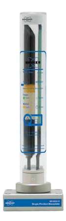
Super Gas Clean Filters
Combination of advanced design and product reliability has resulted in a wide range of gas filters that are customized for challenging applications. Gas purification systems from Bruker are designed to meet specific needs. These systems range from individual to combination filters, from Ultra capacity to Ultra purity, to all-in-one solution kits.Products with innovative features provide a number of advantages to the user. Some of the advantages include:
- High-purity output guarantees 99.9999% pure gas
- Ultra-high capacity for extended life, enhanced productivity
- Glass internals avert diffusion; plastic exteriors ensure safety
- "Quick connect" fittings allow easy, leak-tight filter changes
- Easy-to-read indicators for optimum maintenance and enhanced up-time
All-in-One Solution: Triple Filter Kits for MS/ECD/NPD
The Triple Filter Kit offers a complete solution for purifying carrier gas. It comprises 1 position base plate and 1 Triple (Oxygen/ Hydrocarbon/Moisture) Filter.Complete Filter Set Kit for FID
Fuel Gas Triple Kit for FID
The Fuel Gas Triple Kit is a suitable choice for purifying flame ionization detector (FID) fuel gas and carrier gas, for eliminating hydrocarbons, oxygen and moisture from the carrier gas using the triple filter, and for removing hydrocarbons and moisture from the fuel gas through two combi filters. These combi filters for air and FID Hydrogen create a stable baseline and enhance overall sensitivity and reproducibility.Ultra Capacity Filter Set Kit for FID
This kit is Ultra purity combined with Ultra capacity and includes 1 Ultra High Capacity Hydrocarbon Filter, 1 Ultra High Capacity Oxygen Filter, 1 Ultra High Capacity Moisture Filter, and 2 four position base plates.Fuel Gas Kit for FID
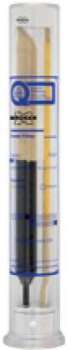
The Fuel Gas Kit is ideal for purifying FID fuel gases and eliminating hydrocarbons and moisture.Moisture Removal
Presence of moisture in carrier gas lines can affect hydrocarbon and oxygen filters and also increase detector noise. As a precautionary measure, a moisture filter can be installed before the oxygen and hydrocarbon filters on all carrier gas lines.
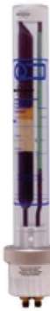
Ultra-High Capacity Oxygen Filter
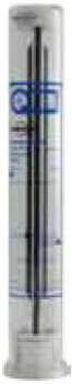
Hydrocarbon Removal
A hydrocarbon filter can be used if the gas has a possible source of hydrocarbon impurities or if carrier gas ghost peaks are observed. The hydrocarbon filter can be installed after the moisture filter so as to prevent the degradation of the hydrocarbon-trapping capability of the activated carbon within the hydrocarbon filter.
Ultra-High Capacity Hydrocarbon Filter
Oxygen Removal
Oxygen is present even in UHP gases and can considerably affect the columns. Even small amounts of leakage at fittings enable oxygen to invade against the concentration gradient. Since oxygen is capable of entering a gas line or during gas bottle exchange, the oxygen filter must be the final connection before the gas line enters the chromatograph.Helium-Specific Triple Filter
High Capacity Helium-Specific Triple Filter
The Helium-Specific Triple Filter is suitable for purifying helium in
GC/ MS systems. It is packed and purged under helium and includes
hydrocarbon, oxygen and moisture filter material in a single filter.Super Clean Gas Filters for LC-MS System
In order to satisfy the high flow requirements of the LC-MS system, the moisture or hydrocarbon filled filters are placed in a parallel fashion. The incoming gas stream is divided uniformly between the filters and the two streams are reconnected after purification but before the gas leaves the base plate.
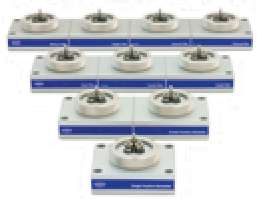
Super Clean Filter Base Plates
Conclusion
Bruker GC columns are available in a variety of stationary phases, column diameters, and capillary column materials. They are suitable for both routine and research analyses. The range of offerings include Standard Wall Coated Open Tubular Columns, Small Internal Diameter Columns, Solid Stationary Phase Porous Layer Open Tubular Columns, and Inert Steel Micro-Packed and Packed Columns.About Bruker
Bruker is the new name in chemical analysis. Accurate and comprehensive analysis of exogenous and discrete elements in a wide range of sample matrices are key applications for many analytical chemistry groups. To address the needs and challenges of analysts working in those areas, Bruker has expanded their product family to provide, and expertly support, a series of fully integrated solutions including:- Gas Chromatography-Mass Spectrometers (GC/MS and GC/MS/MS)
- Inductively Coupled Plasma Mass Spectrometers (ICP-MS)
- Gas Chromatography Systems (GC)
Troubleshooting GC Gas Supply, Sample Preparation, and Inlets
FULL TEXT During 2013 we will present a series of short articles on gas chromatography (GC) troubleshooting and maintenance. In this first installment, we concentrate on the first three important stages in any GC analysis, namely the quality and type of gases supplied to the instrument, key sample preparation considerations, and common problems encountered with the most popular sample inlet for GC: the splitsplitless injector.
Gases commonly used in GC include nitrogen, hydrogen, and helium for the carrier gas, hydrogen for flame ionization detection (FID), and nitrogen, or less favorably helium, as the make-up gas for ionizing detectors. The carrier gas should be free from moisture and oxygen, both of which cause increased stationary-phase bleed, poor peak shape, and reduced sensitivity. Alumina in-line filters (traps) should be fitted as close as possible to the instrument. Self-indicating traps are preferred as the indicator is a tell-tale to signal that the trap is exhausted and needs to be changed. FID and other ionizing detector gases should be free of hydrocarbons that can reduce sensitivity; a hydrocarbon trap is recommended. Other detector types have specific gas purity requirements, and mass spectrometry (MS) detectors, for example, need to have large-capacity oxygen traps fitted. In general, the gases used should be 99.999% pure or better. A periodic "pressure drop" test should be carried out on gas lines to test for leaks in the supply lines - usually achieved by switching off all GC systems, closing the cylinder head regulator (or switching off the gas generator production), and then monitoring the line pressure for a significant pressure drop, which indicates a non-pressuretight line between the gas supply and the instrument.
Sample solvents should be chosen to ensure compatibility with the GC column stationary phase to avoid peak shape effects such as broadening, splitting, and shouldering. Match the sample-solvent polarity with the stationaryphase polarity to avoid these effects: For example, the use of water or methanol as sample solvent with methyl silicone stationary phase or hexane with PEG or Wax phases is not recommended. Different sample solvents produce different volumes of vapor in the inlet, and one should test that the amount of vapor created does not exceed the available volume within the liner; otherwise "backflash" may occur in which analyte is deposited in the carrier gas and septum lines that can lead to carry-over and ir reproducible quantitative results. There is a dedicated software calculator available within CHROMacademy to assist with this test.
Leaking septa give rise to baseline shifts during injection, pressure problems, and poor quantitative reproducibility. Check or replace the septum before each campaign of analyses. Periodically verify the septum purge flow with a flowmeter to avoid noisy baselines with spurious peaks and reduced sensitivity.
The inlet liner should be appropriate to the injection mode and will, over time, become active toward analytes with polar functional groups. The glass wool and quartz glass surface are typically silylated (deactivated) when new; however, the derivatizing reagent hydrolyses over time and exposure to moisture exposes silanol groups, which causes a secondary, unwanted, retention to a proportion of the analyte molecules and, consequently, significant peak tailing. Clean, deactivate, or replace liners or glass wool as necessary to reduce peak tailing and overcome problems with peak area reproducibility.
Ensure that the column is positioned within the inlet according to manufacturers' instructions to avoid problems with quantitative reproducibility.
Clean the inlet walls and any metallic seals at the lower and upper part of the inlet periodically using both polar and nonpolar solvents to ensure good peak shape and quantitative reproducibility.
Periodically check the flow rate of the split gas from the inlet in both the split and splitless (where the flow should be zero) modes with a flowmeter to check for issues with blocking of the split gas lines, the viability and accuracy of the split flow regulator and to test the operation of the solenoid valve that toggles between split and splitless modes.
To optimize peak efficiency (sharp Gaussian peaks), reduce tailing of the solvent peak, and avoid rising baselines during the analysis, ensure that during splitless injection the initial oven temperature is at least 10 0C below the sample solvent boiling point and that the inlet switches to split mode at an optimum time after injection to purge inlet of residual vapors. The optimum split-on (purge) time can be estimated by monitoring peak area with purge times starting at around 20 s after injection and increasing in 10-s steps. The purge time corresponding to the first repeatable peak area measurement should be chosen as the split-on time - that is, if peak areas are reproducible for the 30and 40-s purge times then 40 s is chosen as the split-on time.
Check out the on-line interactive CHROMacademy GC Troubleshooter for a wealth of GC troubleshooting and maintenance information.
Troubleshooting and maintenance of GC Systems
Troubleshooting a GC chromatograph can be made easier, if one learns to
recognize the symptoms produced by an instrument malfunction, column and
detector problems, leaks. Many symptoms appear as unusual peaks as
shown below:
Symptom: No peaks (Fig. 1)
 |
| Fig. 1: No peaks appear after the injection of the sample |
Possible Cause:
Main power off, fuse burned out
Action: Plug in the instrument,
replace fuse
Possible Cause:
Detector off
Action: Turn detector on and adjust
its sensitivity
Possible Cause: No
carrier gas flow
Action: Check the carrier gas lines
and correct the problem i.e. replace empty gas cylinders, possible obstructed
or broken gas lines
Possible Cause:
Injector temperature too low. The sample is not vaporized
Action: Increase injector
temperature.
Possible Cause:
Injector septum is leaking
Action: Replace the septum.
Possible Cause:
The syringe used for the injection of sample is plugged up.
Action: Clean the syringe or replace
it if it is damaged.
Possible Cause:
The FID flame is out.
Action: Check the FID flame. Check
if water vapor condenses on mirror. Light up the flame if needed.
Possible Cause:
Column connections are loose.
Action: Check for leaks. Use a leak
detector. If needed tighten column connections
Possible Cause:
Oven temperature too cold. Possibly, the sample condenses in the column
Action: Increase oven temperature
Symptom: Retention
times or areas are not reproducible (Fig. 2)
Possible Cause:
Septum is leaking
Action: Replace the septum if it is
damaged. If there is a premature septum failure (less than 200 injections)
check also if:
The syringe needle is not straight
The syringe is not installed
correctly
The septum retainer nut is too tight
Possible Cause: Syringe
is dirty or damaged
Action: Replace the syringe if it is
damaged. Clean the syringe with an appropriate solvent if it is dirty.
Possible Cause: Sample
is not stable under the conditions of the analysis
Action: Check the sample stabiblity.
Some samples change with heat or U.V. light. In case the sample is
photosensitive use amber sample vials.
Possible Cause: Sample
volume is too low or too high
Action: Check the sample vials. If
the sample vials are not filled correctly, evaporation or contamination may
affect the analysis. The sample level should be approximately half the volume
of the vial.
 |
Fig. 2: Retention times or areas are not reproducible
|
Symptom: Poor
sensitivity with normal retention time
 |
Fig. 3: Poor sensitivity with normal retention times
|
Possible Cause: Insufficient
sample size
Action: Increase sample size. Check
syringe needle for plugging.
Possible Cause: Poor
sample injection technique
Action: Check if the proper
injection technique is used.
Possible Cause: High
attenuation
Action: Reduce attenuation.
Possible Cause: FID
response low
Action: Optimize the flow rates of H2
and air. Use N2 for make-up gas
Possible Cause: Thermal
conductivity response low
Action: Use higher filament current.
Possible Cause: Syringe
or septum leaking when injecting
Action: Replace syringe and/or
septum
Symptom: Poor
sensitivity with increased retention time and broadening of the peak
Possible Cause: Carrier
gas flow rate too low.
Action: Increase carrier gas flow.
Possible Cause: Septum
is leaking.
Action: Replace septum.
Symptom: Irregular baseline
drift (isothermal)
 |
Fig.4: Irregular baseline drift when operating isothermally
|
Possible Cause: The
instrument location is not according to the manufacturer’s specifications .
Action: Instrument should not be
placed directly under heater or air conditioner or any other place where it is
subject to excessive drafts and ambient temperature changes.
Possible Cause: Column
packing bleeding.
Action: Let column to stabilize as
described by the manufacturer.
Possible Cause: Carrier
gas leaking.
Action: Locate leaks and correct.
Possible Cause: Carrier
gas regulators do not work properly.
Action: Check carrier gas regulators
and flow controllers.
Possible Cause: Poor
air or H2 regulation (FID detectors)
Action: Check regulators and flow
controllers.
Possible Cause: Detector
is contaminated
Action: Clean detector according to
manufacturer’s specifications. Raise temperature and bake out detector
overnight.
Possible Cause: Detector
filaments are defective (TCD detector only)
Action: Change the filaments.
Symptom: Contamination
or ghost peaks
Possible Cause: Vial
cap septum is dissolving in solvent
Action: Check the vial septum. If it
is not resistant enough to the solvent you are using try a more resistant type.
Possible Cause: Injection
port septum is giving off volatiles
Action: Make several blank runs with
a small piece of aluminum foil backing the inlet septum. If the contamination
peaks disappear, they were probably due to the septum. Use another type of
septum that is stable to the required injector temperatures.
Possible Cause: Column
is contaminated
Action: Examine the first 10 cm of
the capillary column for contamination holding a light behind it. If possible
cut the contaminated part of the column. Replace or clean the inlet liner.
Possible Cause: The
sample is not stable
Action: Store the sample in a
protected environment and use amber sample vials.
Symptom: Sinusoidal baseline
drift
 |
Fig.5: Sinusoidal baseline
drift
|
Possible Cause: Oven
temperature defective
Action: Replace the oven temperature
sensing probe .
Possible Cause: Oven
temperature control was set to a low value
Set the oven temperature control to
a higher value.
Possible Cause: Carrier
gas flow regulator defective
Replace the carrier gas flow
regulator. Set to a higher pressure in order to stabilize the gas flow.
Possible Cause: Carrier
gas cylinder pressure too low to allow regulator to work properly
Replace the carrier gas cylinders.
No comments:
Post a Comment