
Ammonia production from natural gas.
- 1. National Fertilizers Ltd. Bathinda AJAY NAGAR 10112001
- 2. Sections Ammonia Plant Urea Plant Steam Generation Plant Bagging Plant
- 3. Ammonia Plant Desulphurization Section Reforming Section Shift Section Carbon Dioxide Removal Section Methanation Section Ammonia Synthesis Section
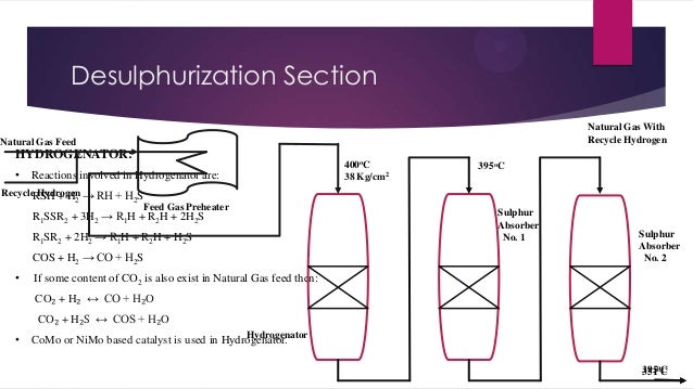
- 4. Desulphurization Section Natural Gas With Recycle Hydrogen Natural Gas Feed HYDROGENATOR: • Reactions involved in Hydrogenator are: Recycle Hydrogen → RH + H S RSH + H2 2 Feed Gas Preheater R1SSR2 + 3H2 → R1H + R2H + 2H2S R1SR2 + 2H2 → R1H + R2H + H2S COS + H2 → CO + H2S • 400oC 38 Kg/cm2 395oC Sulphur Absorber No. 1 Sulphur Absorber No. 2 If some content of CO2 is also exist in Natural Gas feed then: CO₂ + H₂ ↔ CO + H₂O CO₂ + H₂S ↔ COS + H₂O • Hydrogenator CoMo or NiMo based catalyst is used in Hydrogenator. 395oC 351o
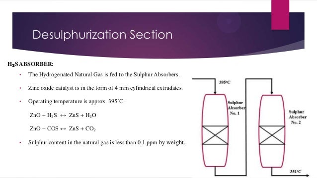
- 5. Desulphurization Section H₂S ABSORBER: • The Hydrogenated Natural Gas is fed to the Sulphur Absorbers. • Zinc oxide catalyst is in the form of 4 mm cylindrical extrudates. • Operating temperature is approx. 395˚C. ZnO + H₂S ↔ ZnS + H₂O ZnO + COS ↔ ZnS + CO₂ • Sulphur content in the natural gas is less than 0.1 ppm by weight.
- 6. Reforming Section Desulphurized gas is converted into synthesis gas by catalytic reforming of the hydrocarbon mixture with steam and the addition of air. Reactions involve in Reformer Section: CnH2n+2 + 2H₂O ↔ Cn-1H2n + CO₂ + 3H₂ - heat CH₄ + 2H₂O ↔ CO₂ + 4H₂ - heat CO₂ + H₂ ↔ CO + H₂O – heat Reactions take place in two steps 1. Primary reforming 2. Secondary reforming
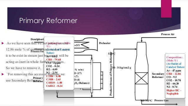
- 7. Primary Reformer Process Air Preheater Product Stream of Primary Reformer Desulphurized Gas As we have seen that we areComposition : (Mole getting around Steam Carbon Mole Ratio=3/1 %) 12.86 mole % of methane and we don’t want (At Inlet of Catalyst Process Steam Tubes) it to be exist in stream just because it will be Ar – 0.02 CH4 – 79.68 acting as inert in whole further processes. CO – 2 ppm CO2 – 0.24 So we have to remove it. Composition of catalyst (% w/w) H2 – 4.09 N2 – 2.54 1. Nickel Monoxide, NiO (17) `For removing this access of methane we C2H6 – 6.48 2. Calcium Oxide, CaO (7) Primary Potassium use Secondary Reformer. 3.C3H8 – 2.63 oxide, K2O (4) Reformer C4H10 – 1.88 4. Aluminum Oxide, Al2O3 (Balance) C6H12 - 0.24 520oC 34 - 31 kg/cm2 g Composition: (Mole %) (At Outlet of Catalyst Tubes) Ar – 47 ppm Secondary CH4 – 12.86 Reformer CO – 9.5 CO2 – 10.70 H2 – 66.20 N2 – 0.74 Higher HC – Neglegible 785-795oC Process Gas
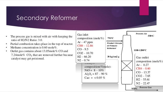
- 8. Secondary Reformer • • • • The process gas is mixed with air with keeping the ratio of H2/N2 Ratio: 3.0. Partial combustion takes place in the top of reactor. Methane concentration is 0.60 mole%. Outlet gas contains about 13.05mole% CO and 7.24mole% CO₂ that are removed further because catalyst may get poisioned. Gas inlet composition (mole%) 791oC Ar – 47 ppm CH4 – 12.86 CO – 9.5 CO2 – 10.70 30 kg/cm2 g H2 – 66.20 N2 – 0.74 Catalyst composition(%mole): NiO = 8 – 10% Al2O3 = 87 – 90 % Cao = < 0.05 % 550oC 1100-1200oC Gas outlet composition (mole%) Ar – 0.27 CH4 – 0.60 CO – 13.37 CO2 – 7.65 H2 – 55.61 N2 – 22.47 958oC
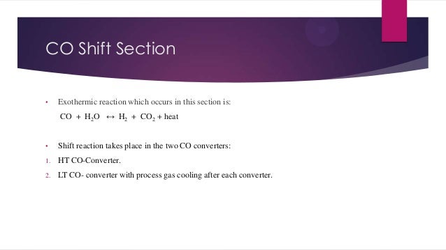
- 9. CO Shift Section • Exothermic reaction which occurs in this section is: CO + H2O ↔ H2 + CO2 + heat • Shift reaction takes place in the two CO converters: 1. HT CO-Converter. 2. LT CO- converter with process gas cooling after each converter.
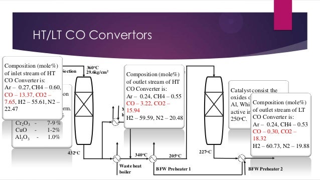
- 10. HT/LT CO Convertors Composition (mole%) Process of inlet gas from of HT Section stream Reformer CO Converter is: Ar – 0.27, CH4 – 0.60, CO Catalyst’s composition – 13.37, CO2 – (mole%) which is 7.65, H2 – 55.61, N2 – HT CO available in pellet form. 22.47 Fe2O3 85- Convertor 95 % Cr2O3 7-9 % CuO 1-2% Al2O3 1.0% 432oC 360oC 29.6kg/cm2 205oC 28.6kg/cm2 (mole%) Composition of outlet stream of HT CO Converter is: Ar – 0.24, CH4 – 0.55 CO – 3.22, CO2 – Methanator trim 15.94 heater H2 – 59.59, N2 – 20.48 340oC Waste heat boiler 205oC BFW Preheater 1 Catalyst consist the oxides of Cu, Cr and Composition (mole%) LT CO Al, Which is most Convertor of outlet stream of LT active in between 170250oC. CO Converter is: Ar – 0.24, CH4 – 0.53 CO – 0.30, CO2 – 18.32 H2 – 60.73, N2 – 19.88 227oC 160oC BFW Preheater 2
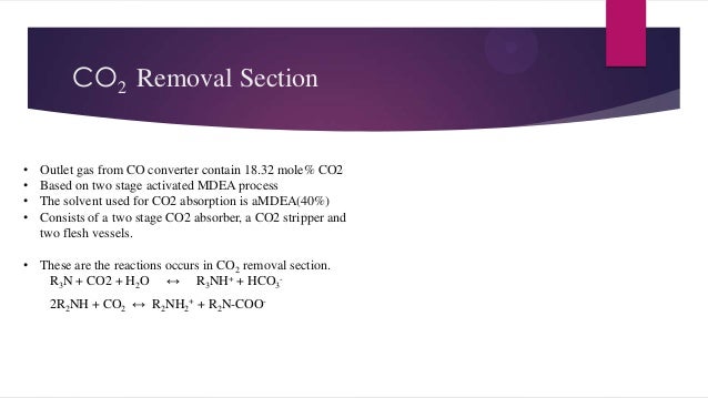
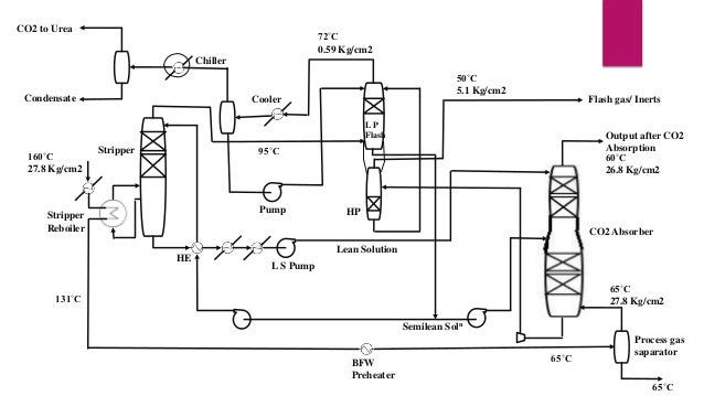
- 11. CO2 Removal Section • • • • Outlet gas from CO converter contain 18.32 mole% CO2 Based on two stage activated MDEA process The solvent used for CO2 absorption is aMDEA(40%) Consists of a two stage CO2 absorber, a CO2 stripper and two flesh vessels. • These are the reactions occurs in CO2 removal section. R3N + CO2 + H2O ↔ R3NH+ + HCO32R2NH + CO2 ↔ R2NH2+ + R2N-COO-
- 12. CO2 to Urea 72˚C 0.59 Kg/cm2 Chiller Condensate 50˚C 5.1 Kg/cm2 Cooler Flash gas/ Inerts LP Flash 160˚C 27.8 Kg/cm2 Output after CO2 Absorption 60˚C 26.8 Kg/cm2 95˚C Stripper Pump Stripper Reboiler HP CO2 Absorber HE Lean Solution L S Pump 65˚C 27.8 Kg/cm2 131˚C Semilean Soln BFW Preheater 65˚C Process gas saparator 65˚C
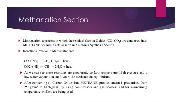
- 13. Methanation Section Methanation, a process in which the residual Carbon Oxides (CO, CO2) are converted into METHANE because it acts as inert in Ammonia Synthesis Section. Reactions involve in Methanator are: CO + 3H2 ↔ CH4 + H2O + heat CO2 + 4H2 ↔ CH4 + 2H2O + heat As we can see these reactions are exothermic so Low temperature, high pressure and a low water vapour content favours the methanation equilibrium. After converting all Carbon Oxides into METHANE, product stream is pressurised from 25Kg/cm2 to 187Kg/cm2 by using compressors and gas boosters and for maintaining temperature, chillers are being used.
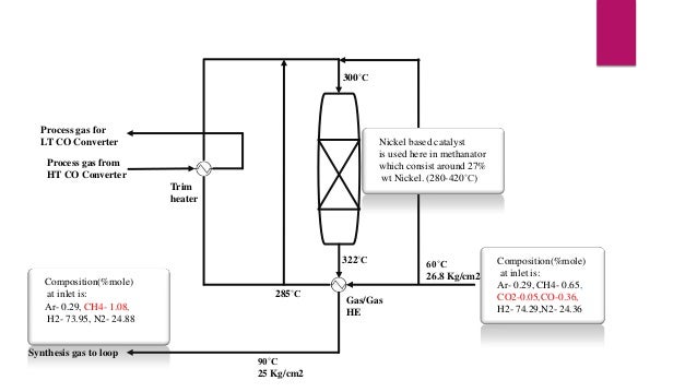
- 14. 300˚C Process gas for LT CO Converter Nickel based catalyst Methanator is used here in methanator which consist around 27% wt Nickel. (280-420˚C) Process gas from HT CO Converter Trim heater 322˚C Composition(%mole) at inlet is: Ar- 0.29, CH4- 1.08, H2- 73.95, N2- 24.88 Synthesis gas to loop 285˚C 90˚C 25 Kg/cm2 Gas/Gas HE 60˚C 26.8 Kg/cm2 Composition(%mole) at inlet is: Synthesis Gas From Ar- 0.29, CH4- 0.65, CO2 Removal Section CO2-0.05,CO-0.36, H2- 74.29,N2- 24.36
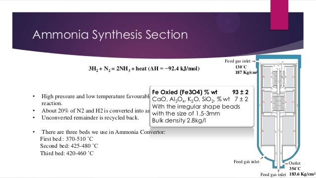
- 15. Ammonia Synthesis Section 3H2 + N2 = 2NH3 + heat (ΔH = −92.4 kJ/mol) • • • • Feed gas inlet 130˚C 187 Kg/cm2 Fe Oxied (Fe3O4) % wt 93 ± 2 High pressure and low temperature favourable equilibrium conditions of ammonia CaO, Al2O4, K2O, SiO2, % wt 7 ± 2 reaction. With the irregular shape beads About 20% of N2 and H2 is converted into ammonia at given operating conditions. with the size of 1.5-3mm Unconverted remainder is recycled back. Bulk density 2.8kg/l There are three beds we use in Ammonia Convertor: First bed : 370-510 ˚C Second bed: 425-480 ˚C Third bed: 420-460 ˚C Feed gas inlet Outlet 354˚C Feed gas inlet 183.6 Kg/cm2
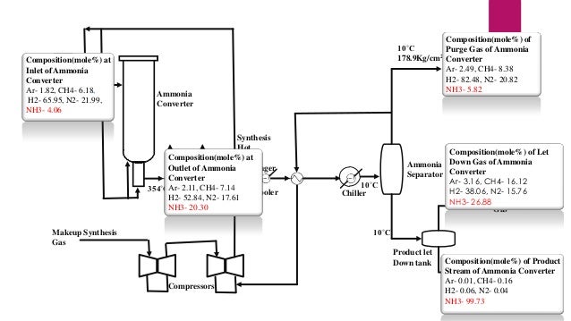
- 16. Composition(mole%) of 10˚C Purge Gas of Ammonia 2 178.9Kg/cm Converter Purge Gas Ar- 2.49, CH4- 8.38 H2- 82.48, N2- 20.82 NH3- 5.82 Composition(mole%) at Startup Ammonia Inlet of Heater Converter Ar- 1.82, CH4- 6.18, 130˚C H2- 65.95, N2- 21.99, 2 NH3- 4.06 187Kg/cm Ammonia Converter Synthesis Hot Composition(mole%) at Heat Steam Outlet of Ammonia Exchanger HE Boiler Converter 354˚CAr- 2.11, CH4- 7.14 270˚C 180˚C Cooler H2- 52.84, N2- 17.61 NH3- 20.30 10˚C Chiller Composition(mole%) of Let Ammonia Down Gas of Ammonia Separator Converter Ar- 3.16, CH4- 16.12 11˚C H2- 38.06, N2- 15.76 27Kg/cm2 Let Down NH3- 26.88 Gas 10˚C Makeup Synthesis Gas Product let Down tank Compressors Composition(mole%) of Product Ammonia Stream of Ammonia Converter (Product) Ar- 0.01, CH4- 0.16 12˚C H2- 0.06, N2- 0.04 25Kg/cm2 NH3- 99.73
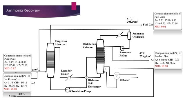
- 17. Ammonia Recovery 61˚C 20Kg/cm2 Composition(mole%) of Fuel Gas: Ar- 2.71, CH4- 9.46 Fuel Gas H2- 65.73, N2- 22.08 NH3- 0.01 Ammonia OH Drum Purge Gas Absorber Composition(mole%) of Purge Gas: Ar- 2.49, CH4- 8.38 H2- 82.48, N2- 20.82 10˚C NH3- 5.82 178.9Kg/cm2 Purge Gas Composition(mole%) of Let Down Gas Let Down Gas: 11˚C Ar- 3.16, CH4- 16.12 27Kg/cm2 H2- 38.06, N2- 15.76 NH3- 26.88 Steam 248˚C Distillation Column Ammonia Reflux Lean Soln Cooler Richlean Soln Exchanger Circulation Pump Reboiler 45˚C Composition(mole%) of 2 25Kg/cm Product Gas: Ar- 64ppm, CH4- 0.03 Ammonia H2- 0.06, N2- 0.02 NH3- 99.88
- 18. Conclusion National Fertilizer Ltd. Bhatinda is producing 99.80% pure Ammonia by Using Natural Gas with the help of helder tropsch method for further production of Urea.
- 19. “ Thank You !!! ”
This comment has been removed by a blog administrator.
ReplyDeleteSteelman Gases Pvt. Ltd. is a trusted provider of Ammonia Gas, Ammonia Solution, Chlorine Gas , and Sodium Hypochlorite for various industries. As reliable Sodium Hypochlorite Solution Manufacturers, we ensure our products meet the highest quality and safety standards. With a focus on innovation and customer satisfaction, Steelman Gases Pvt. Ltd. is your go-to partner for top-quality Ammonia Gas, Ammonia Solution, Chlorine Gas, and Sodium Hypochlorite products.
ReplyDelete