Source http://www.owlnet.rice.edu
Abstract
In this project, the heat exchange system for the reforming section of an ammonia plant was optimized. The system consists of a single shell and tube process/process exchanger followed by a secondary cooling water exchanger. The primary exchanger heats the main feed before it enters the primary reformer, from 231.1 °C to 600 °C. It is exchanged with the hot stream from the secondary reformer which is cooled from 995.8 °C to 741 °C. The secondary heat exchanger is used to further cool the hot stream from 741 °C to 250 °C.The exchanger system was modeled in Aspen using the Peng Robinson - Boston Mathias property set and the HeatX module. The primary heat exchanger transfers 19.8 MMKcal/hr, and the heater uses 35.7 MMKcal/hr. Rigorous analysis in Aspen was performed on the primary exchanger specified as TEMA type CFU, class R. The heat exchanger was costed by Aspen at $151,400, with the shell and tube constructed of Incoloy, 800 series.Introduction
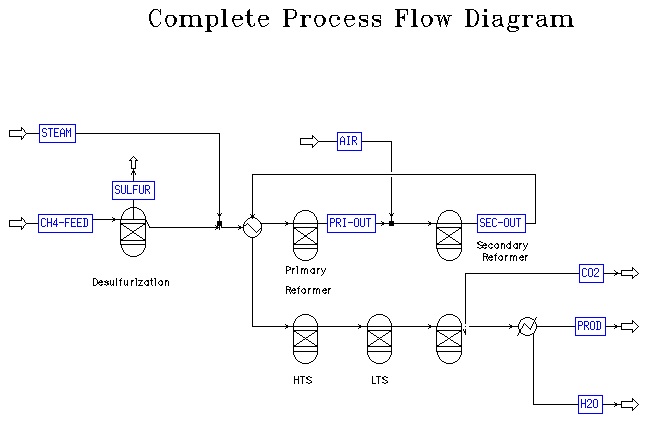
Ammonia production involves two primary operations, the reforming and the synthesis processes. Ammonia reforming takes a feed of natural gas and steam. The typical units for this process, as discussed in class and the literature, are the desulfurization unit, primary reformer, secondary reformer, high temperature water gas shift, low temperature water gas shift, carbon dioxide absorber, water condenser, methanator, and a second water condenser. A diagram of the overall process, obtained from the reactors group, can be found in Appendix A. The reaction in the primary reformer is very endothermic, so the feed to this unit must be heated before entry. The secondary reformer is operated adiabatically and further heats the stream. This stream must be cooled before continuing on to the other units in the plant, such as the carbon dioxide absorber. There is a rather significant range of temperatures required for this complex process, making efficient heat exchange a primary concern. Special considerations for materials and exchanger class were necessary in the detailed design of the primary heat exchanger due to the high temperatures and pressures in this system.Overall Process
Overall Process The primary focus of this project was to design an efficient and cost effective heat exchange system for the reforming end of an ammonia plant. Comparison between the optimum system and a pure utility-based heating and cooling design was also completed. The guidelines for the project required the combined use of the previous two projects detailing the reactors and the separation system. Utilizing these designs, a somewhat simplified system was agreed upon for the project scope. The system under consideration has two streams in need of heating and cooling. The hot stream runs from the secondary reformer to the absorber at a pressure of 35.29 bar. It is a vapor stream consisting primarily of steam, H2, and N2, with small amounts of CO, CO2, CH4 and Ar. It requires cooling from 995.8 °C to 250 °C. The cold stream is the combined feed of methane and steam that needs to be heated before entering the primary reformer. Its primary constituents are steam and CH4, with traces of CO2 and N2, and it must be heated from 231.1 °C to 600 °C, at 39.22 bar. The actual compositions of the streams from the previous projects used in this system are given in Appendix B. The temperature requirement for the stream going to the absorber was taken from the separators project, and the remaining stream specifications were from the reactors project.In choosing a property set for simulation, the NRTL equation was considered initially because it is commonly used in industry and acedemia. However, the recommended conditions for its use were not applicable to the system under consideration. After researching other available property sets in Aspen, it was determined that the Peng Robinson - Boston Mathias (PR-BM) property set best suited the needs of the system. The PR-BM property set is commonly used for gas processing, especially for mixtures of light gases, such as H2 and CO2. Reasonable results are expected at all temperatures and pressures with the PR-BM property set, an important consideration given the extreme temperatures and pressures of the reforming system.
Aspen Model
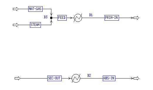
The heat exchange needs for the system and the optimum system design were considered using Aspen's simulation capabilities. The first task completed in Aspen was the analysis of the two individual streams in the process that needed to be heated and cooled. As shown in Appendix C, two heater modules were used. The first cooled the hot stream from 995.8 °C to 250 °C with a heat duty of 19.79 MMKcal/mol. The second heated the cold stream from 231.1 °C to 600 °C using 55.66 MMKcal/mol. A sensitivity run was utilized to determine the enthalpy of each system over the appropriate temperature range. This data was then analyzed in Matlab; see the next section for details. There were no pinch points and no stream crossings, so the system is relatively simple thermodynamically. There was not enough duty available in the cold stream to cool the hot stream to the necessary 250 °C. A cooler needed to be added to the system, either prior to the heat exchanger to start the cooling process, or following the heat exchanger to complete the cooling of the hot stream. The latter was chosen because the temperature difference between the hot and the cold streams was much less than that of the cooling water and the hot stream. The lower temperature difference is desired to reduce wear on the exchanger. Figure 1 shows the diagram of these two exchangers as modeled. |
Figure 1: Optimum Exchanger Model
Once the exchanger system was decided upon, a rigorous analysis of the primary heat exchanger was necessary. The exchanger was specified as TEMA type CFU, class R. Type C allows for a removable tube bundle, type F specifies a two pass shell, and type U specifies a U-tube bundle (Gas 9-15). A diagram of what this exchanger might look like is included in Figure 2. Class R allows for extreme conditions, such as the high temperatures and pressures of this system, by designating conservative calculations (Branan 22). The removable tube bundle allows the tubes to be cleaned easily, which would most likely be done by hydroblasting. Access for cleaning is essential to the function of the system. U-tubes were chosen because they allow for expansion of the tube bundle. Material expansion is an important consideration in our system given the large temperature difference between the hot and cold streams (Branan 24). If a fixed tube sheet were used, an expansion joint would be necessary (Branan 25). Expansion joints are costly and a potential source of hazardous leaks. The two pass shell design is most common and delivers higher efficiency in heat exchange. In order to minimize the necessary utility costs, maximum cooling must occur in the exchanger, and this is assured with the two pass shell design.
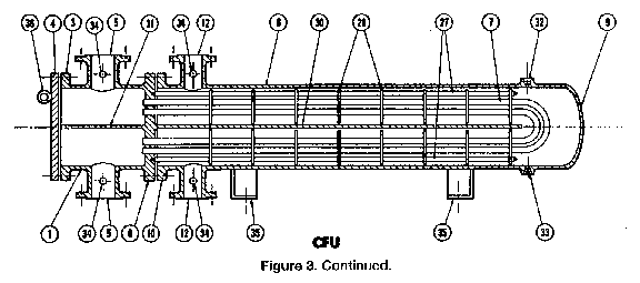 |
Figure 2: CFU Type Exchanger Drawing
The surface area necessary for this exchange was calculated by Aspen to be 120.2 m2. Then, the number and size of the tubes was calculated to support the required heat exchange area. The optimal system consisted of a tube sheet of 100, 1.5 inch diameter, 36 foot long tubes with a 4.5 inch pitch and arranged in a triangular pattern. The 4.5 inch pitch is slightly greater than minimum, because the shell-side flow is large (Branan 29). The baffles were placed 2 feet apart to allow for optimal flow on the shell side and adequate tube bundle support (Perry 11-42). The nozzle sizes were determined to be 12" shell side and 10" tube side by finding the smallest nominal size which gave reasonably low pressure drops and fluid velocities (Branan 26-29). The pressure drop data can be found in Appendix B. These specifications lead to a heat exchanger that is 52 inches in diameter and 36 feet in length, with additional length required for the channel end (the left side of Figure 2).
Matlab Model
Matlab was used to get a basic understanding of the system, plan a heat exchanger solution, and verify the results from Aspen. First, sensitivity runs from Aspen were used to get the enthalpies at the full range of temperatures for each stream. Then that data was exported into Matlab where the curves were plotted and the cold stream shifted so that its high enthalpy end would be flush with the high enthalpy end of the hot stream. That kept the lines from intersecting, gave a maximum temperature difference between the two streams, and required only one utility heat exchanger. Next, the curves were approximated with straight lines of slopes equal to the average of the end slopes, and figure 3 shows that these are very close approximations.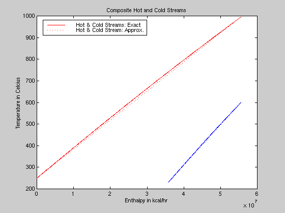 |
Figure 3: Composite Curves

Lastly, the first program was run again using the U from the rigorous Aspen model to find a surface area of 114.7 m2 (which closely matches Aspen's value) and the following graph for a one-pass heat exchanger.
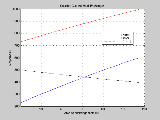 |
Figure 4: Temperature Profile
Cost Analysis and Future Considerations
The primary heat exchanger in this system was costed by Aspen at $151,400. The area predicted by Aspen using this exchanger was rather large, so alternate systems were explored. A system of two, serial shell and tube heat exchangers was simulated. The division of the heat duty among the two exchangers was difficult to determine, but a few simple variations (50/50, 75/25, etc.) were tried. With a half and half division of duty, the cost of the two exchangers was given by Aspen as $165,200 which is 9% more than the single exchanger. When considering space availability and layout in individual plants, this system should definitely be explored further. Various tube number and length combinations were simulated. Fewer, longer tubes created an excessively long exchanger and increased the cost of the unit, while a greater number of shorter tubes led to pressure drops and velocities that were too high in the tubes. Once again, given the specific space requirements of the individual plant, these alternate systems should be considered further. Whether the exchanger should be vertical or horizontal is also a decision that should be made later when the plant plot arrangement and available support/access structures around the unit are known.For cost analysis purposes, the cost of purely utility supported heating and cooling systems was compared to the optimum exchanger system design. Heating the cold stream from 231.1 °C to 600 °C requires 19.79 MMKcal of duty which costs $180 per hour ($1,578,966 per year) in steam. This estimate comes from Dupont's Victoria plant steam cost of $2.30 per million Btu. There are some cooling water requirements in the optimum design for the final cooling of the hot stream, but the cost of cooling water is insignificant in comparison to steam. Essentially it is only the cost of the treatment and the pumping. The amount of cooling water required has been reduced through the integration of the heat system.
Conclusions
This optimum heat exchange system was designed with many important considerations. The system was based on efficiency of design. Operational conditions, including materials of construction, and maintenance requirements were also important factors. Overall, the savings just on steam justify the use of the process/process exchanger designed by this team.References
Bird, Stewart, and Lightfoot. Transport Phenomena. John Wiley and Sons, Inc. New York.1960. pp. 399.Branan, Carl R. Rules of Thumb for Chemical Engineers. Gulf Publishing Company.
Houston. 1994. pp. 19-30, 231-235.Gas Processors Association. "Heat Exchangers." Engineering Data Book, Volume I. Gas
Processors Suppliers Association. Tulsa, OK. 1987. Section 9, pp. 1-18.Perry, Robert H. and Green, Don W. Perry's Chemical Engineer's Handbook. McGraw-
Hill. New York. 1997. pp. 11-33, 11-42, 28-50, 28-64.
Appendix A- PFD for Reforming in an Ammonia Plant
 |
Appendix B- Stream Compositions
| FEED | PRIM-IN | SEC-OUT | HOT-OUT | ABS-IN | |
|---|---|---|---|---|---|
| Temp (°C) | 231.1 | 600 | 995.8 | 741.0 | 250.0 |
| Pressure (bar) | 39.22 | 38.75 | 35.29 | 34.647 | 35.29 |
| Vapor Fraction | 1.00 | 1.00 | 1.00 | 1.00 | 1.00 |
| Enthalpy (MMkcal/hr) | -231.935 | -212.135 | -154.969 | -174.768 | -210.383 |
| Mole Flow (kmol/hr), total | 5004.443 | 5004.443 | 8828.312 | 8828.312 | 8828.312 |
| CH4 | 1250.0 | 1250.0 | 21.281 | 21.281 | 21.281 |
| H2O | 3750.0 | 3750.0 | 2832.839 | 2832.839 | 2832.839 |
| H2 | - | - | 3374.600 | 3374.600 | 3374.600 |
| CO | - | - | 814.477 | 814.477 | 814.477 |
| CO2 | 3.000 | 3.000 | 417.242 | 417.242 | 417.242 |
| N2 | 1.443 | 1.443 | 1350.593 | 1350.593 | 1350.593 |
| Ar | - | - | 17.280 | 17.280 | 17.280 |
Appendix C- Utility Heat Exchangers Model
No comments:
Post a Comment